
Views: 0 Author: Site Editor Publish Time: 2026-06-26 Origin: Site


Air handling units serve as the lungs of modern commercial facilities. At the heart of these massive systems lies the fan, a critical component driving both performance and operational costs. In typical building HVAC systems, fans alone account for up to 60% of total energy consumption.
Technical buyers often face severe risks when selecting equipment based purely on "free-air" catalog data. This oversight routinely results in catastrophic efficiency losses, disruptive acoustic resonance, or premature failure. These failures compound rapidly when integrating standard units into complex, high-impedance duct networks.
This guide provides an evidence-based framework for evaluating and sizing fans correctly. You will learn to navigate total system impedance, compare modern motor efficiencies, and address harsh environmental realities. We aim to equip you with actionable strategies to specify the ideal fan for your precise engineering constraints.
Free-air data is deceptive: System impedance (filters, coils, dampers) drastically alters real-world fan performance.
Beware the "Safety Factor" trap: Arbitrarily inflating static pressure requirements by 20–30% leads to oversized fans, surging airflow, and wasted energy.
Motor technology dictates ROI: Transitioning from traditional belt-driven AC fans to direct-drive EC ventilation fans significantly improves low-load efficiency and removes mechanical maintenance.
Redundancy mitigates risk: Fan arrays offer fail-safes that single-large-fan configurations cannot provide.
A fan represents a massive portion of your facility's long-term energy footprint. Initial capital expenditure rarely reflects the true operational weight of the equipment. Instead, lifetime energy usage dwarfs upfront costs. Focusing on robust airflow efficiency during partial load conditions prevents excessive energy drain. Most systems rarely run at 100% capacity continuously. They modulate based on occupancy and weather variables. An efficient fan operates cleanly at these reduced speeds without burning unnecessary power.
Maintenance realities further distinguish different fan selections. Traditional belt-driven systems demand constant oversight. Maintenance crews must perform regular belt tensioning to prevent slip. They must routinely lubricate bearings and align pulleys. These tasks consume labor hours and introduce physical wear. Contrast this high-maintenance nature with the operational predictability of direct-drive systems. Direct-drive configurations eliminate belts entirely. They reduce moving parts, which drastically lowers the ongoing maintenance burden.
System reliability introduces another crucial operational impact. Relying on a single massive fan creates a catastrophic single point of failure. If this primary fan breaks down in mission-critical environments like hospitals or data centers, the entire cooling infrastructure collapses. Modular fan arrays mitigate this risk. By installing a parallel wall of smaller fans, you build inherent resilience into the system. If one fan fails, the others ramp up speed slightly to compensate. This redundancy ensures zero operational downtime during unexpected hardware faults.
Manufacturers typically list performance data using Standard Cubic Feet per Minute (SCFM). SCFM assumes standard sea-level conditions with an air density of 0.075 pounds per cubic foot. However, actual operating conditions rarely match these perfect laboratory parameters. You must convert these figures into Actual CFM (ACFM) to understand true performance.
You must apply altitude and temperature corrections to calculate ACFM accurately. Higher altitudes and elevated temperatures lower air density. We refer to this as the rarefication factor. Less dense air carries less mass. Because air density directly impacts the fan's ability to move heat, a fan rated for 10,000 SCFM will move significantly less thermal energy in a high-altitude location like Denver compared to Miami. Ignoring the density variable guarantees an undersized fan.
Total System Static Pressure defines the resistance your fan must overcome to push air through the system. Friction from ductwork, densely pleated HEPA filters, cooling coils, and louvered dampers all contribute to this resistance. Calculating this friction accurately remains one of the most critical steps in engineering an air handling system.
Engineers often fall into a crucial engineering pitfall: the over-specification trap. Many professionals add a large "safety factor" to their static pressure calculations just to be safe. It is common to see a 30% arbitrary buffer added to the final number. This practice creates severe operational problems. When you select a fan for an artificially high static pressure, it will over-deliver air when the real-world resistance turns out to be lower.
This over-delivery destroys system efficiency. It causes motor strain, excessive noise, and surging airflow that destabilizes downstream controls. To avoid this trap, calculate static pressure meticulously using actual component pressure drops. Keep your safety margins below 8% to maintain optimal performance.
Scenario | Calculated Static Pressure | Safety Margin Applied | Real-World Operational Result |
|---|---|---|---|
Accurate Engineering | 4.0 in. wg | 5% | Smooth operation, optimal energy use, balanced airflow. |
Over-Specification Trap | 4.0 in. wg | 30% | Surging airflow, high noise, massive efficiency loss. |
Traditional Alternating Current (AC) motors have dominated the industry for decades. They offer a low initial cost. Their ubiquitous nature makes them highly familiar to older mechanical contractors and maintenance teams. Most standard replacement parts remain easily accessible.
Despite these advantages, AC motors present significant cons. They suffer from inherent energy losses inside the motor and belt assembly. Mechanical friction wastes power before it ever turns the impeller. Furthermore, controlling their speed introduces operational limitations. Standard Variable Frequency Drives (VFDs) often cannot run efficiently below 25Hz. Dropping below this frequency threshold causes severe low-frequency energy waste. It also induces significant motor heating, which degrades the internal insulation and shortens equipment life.
Electronically Commutated (EC) motors represent the modern standard for high-performance air handling. They combine standard AC power inputs with a built-in DC motor and integrated electronics. This hybrid design offers frictionless speed control without requiring an external VFD.
The primary drawback is a higher upfront cost. Procurement budgets take a larger initial hit compared to basic AC setups. However, the application fit makes them incredibly valuable. They serve as ideal air handling unit fans for variable-demand systems. They provide precise, continuous modulation down to 10% speed without overheating. This high aerodynamic efficiency makes them perfect for modern, energy-conscious building designs.
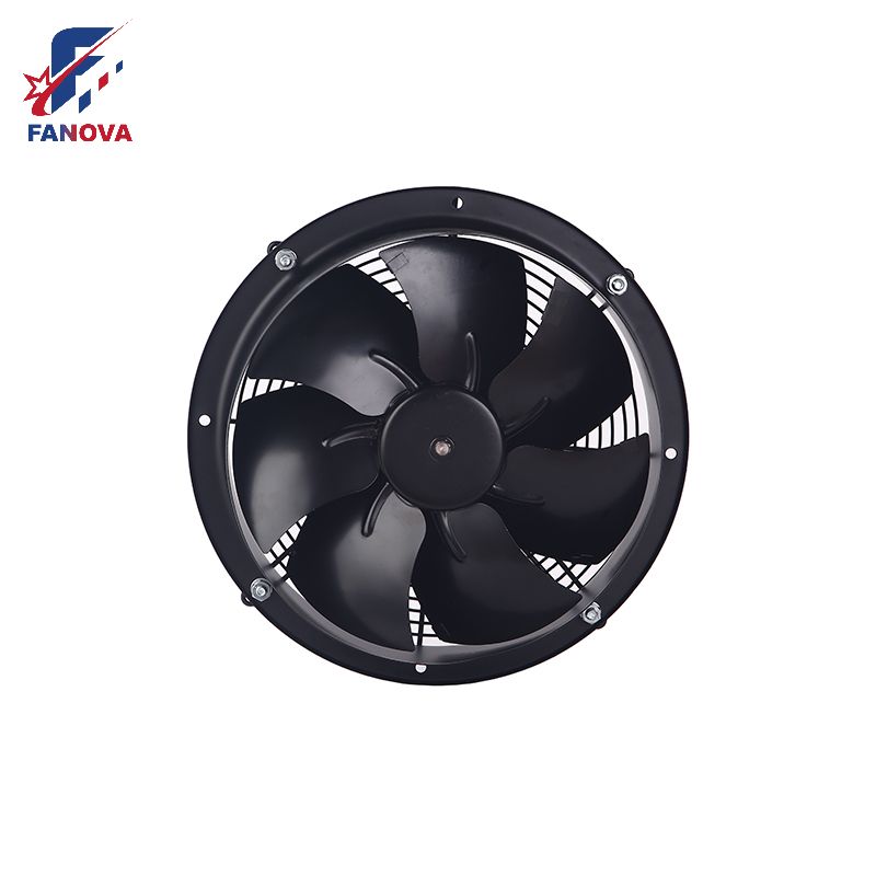
Axial fans utilize a propeller-like design. They draw air in and push it out parallel to the rotating shaft. Their physical footprint remains relatively small for the amount of air they handle.
These models feature specific limitations. They prove excellent for high-volume, low-resistance environments. You see them frequently in free-air applications like condenser cooling or warehouse wall ventilation. However, they are generally unsuitable for the high static pressure environments found inside ducted AHUs. Dense filters and cooling coils create too much resistance for an axial impeller to overcome efficiently without stalling.
Centrifugal fans pull air in axially and discharge it radially at a 90-degree angle. This configuration acts as the industry standard for overcoming heavy duct system resistance. They generate substantially higher pressure profiles than axial counterparts.
You must evaluate various impeller sub-types when selecting a centrifugal AHU fan:
Forward-curved: These impellers feature blades curving toward the direction of rotation. They remain good for clean air environments and compact spaces. However, they are mechanically less efficient and can overload the motor if system resistance drops unexpectedly.
Backward-inclined / Aerofoil: These blades lean away from the direction of rotation. They stand as the highest efficiency choice for clean-air AHUs. They possess a "non-overloading" power curve, meaning power consumption drops naturally as airflow maxes out, protecting the motor from burning out.
Impeller Type | Best Application | Efficiency Level | Motor Overload Risk |
|---|---|---|---|
Axial | Free-air, no ducts | High at low pressure | Low |
Forward-Curved Centrifugal | Compact AHUs, low pressure | Moderate | High |
Backward-Inclined Centrifugal | Heavy ducting, variable flow | Very High | None (Non-overloading) |
Noise represents far more than just a dB number printed on a specification sheet. Acoustics and resonance interact heavily with the surrounding physical structure. Inlet conditions play a massive role here. If ductwork bends too sharply before entering the fan, the turbulent air generates harsh aerodynamic noise. Mounting frames and operating RPMs also interact to create structure-borne noise. This low-frequency vibration travels through concrete floors and bothers building occupants.
You must address mounting and vibration during the design phase. Basic rubber mounts degrade quickly and fail to isolate low-frequency vibrations. We highly recommend using specialized spring isolators paired with rigid metal frames. This combination decouples the spinning mass from the building structure and significantly extends the lifespan of the equipment.
Harsh environments demand specific component upgrades. Do not deploy standard commercial fans into industrial process areas. Outline necessary upgrades based on environmental threats. For explosive environments, you need spark-proof designs utilizing non-ferrous impellers. Corrosive air applications require wash-down motors and specialized epoxy coatings. If your application exceeds 120°C, you must specify heat slingers to dissipate thermal energy and protect the main bearings from failing prematurely.
Finally, always mandate strict standards and certifications. Never trust unverified catalog data. Recommend shortlisting manufacturers who adhere strictly to verified testing standards. Look for certifications like AMCA, AHRI G I-P, or DIN EN ISO 5802. These organizations verify that the catalog claims actually match the real-world output under controlled testing conditions.
Navigating the procurement process requires a methodical approach. Follow this structural framework to align your equipment specifications with actual engineering constraints.
Calculate actual operating constraints: Determine your ACFM accurately by adjusting for local altitude and maximum temperature variables. Calculate precise static pressure based on actual duct friction and component pressure drops. Exclude excessive safety buffers that inflate the requirement past 8%.
Determine spatial and redundancy requirements: Analyze the physical footprint inside the air handler. Decide whether you will use one large backward-inclined centrifugal fan or a parallel wall of compact EC fans for built-in redundancy.
Evaluate control integration and feedback: Match the motor electronics to your building management system. Specify the required control signal type (PWM, 0-10V, or Modbus). Confirm necessary feedback requirements, such as a tachometer output (FG) for speed monitoring or an alarm relay (RD) for failure detection.
Request verified performance curves: Ask the manufacturer to provide a detailed performance curve showing your specific operating point. Do not accept a generic chart showing only peak efficiency points. Verify that your designated operating point falls within the stable, high-efficiency zone of the fan curve.
Fan selection remains a complex, system-level engineering decision rather than a simple part replacement exercise. Sizing errors or improper motor selections cascade throughout the entire mechanical network, degrading performance at every level. Relying strictly on actual operating data ensures you avoid the pitfalls of free-air catalogs and arbitrary safety factors.
Optimizing the HVAC Fan specification directly correlates to long-term operational stability and energy compliance. Embracing advanced direct-drive technology and redundancy-focused layouts eliminates maintenance headaches while maximizing system uptime.
Before finalizing any procurement spec, consolidate your ACFM calculations, total static pressure data, and physical space constraints. Consult directly with an applications engineer to validate your operating points against verified AMCA or ISO performance curves. Rigorous upfront evaluation guarantees peak performance and secures your operational investments for the future.
A: Generally no. Axial fans excel in zero-duct, high-volume scenarios. AHUs have high internal static pressure due to dense filters, cooling coils, and dampers. This heavy resistance requires the stronger pressure capabilities of centrifugal or mixed-flow designs to prevent airflow stalling.
A: Catalog data is often based on ideal "free-air" conditions inside standardized test chambers. Real-world performance drops sharply due to total system impedance, poor inlet duct design (system effect), and air density changes caused by altitude and high temperatures.
A: EC fans completely eliminate the mechanical friction losses of belt drives and the electrical losses associated with external VFDs. They maintain significantly higher efficiency at partial speeds and eliminate low-frequency overheating, all while taking up less physical footprint inside the AHU.


